Saturday, 27 April 2013
enGinEerinG daY
CONCLUSION
This day is the presentation day and be called as Engineering Day. All the final year student will present their project to the accesors. It a quit though day since that I have n my fiend have to be there at 8am until 5pm. I got Mdm Ziany and Sir Razak. Their question is a bit though and I almost drown by their questions and Alhamdulillah, I pass through it.
Wednesday, 17 April 2013
Tr0ubLe sHo0tinG
OBJECTIVE
METHOD
- To study the circuit
- To troubleshoot the circuit
- To observe the output graph
METHOD
- Combine all the circuit and connect to the DAQ and LabVIEW
- The step is same with before
- Troubleshoot the circuit to find problems that occurs
- The output (graph) being observed and save for further references
RESULT
Figure 1: Circuit Connection
Figure 2: LabVIEW II
CONCLUSION
For this week, I have do the troubleshooting for my project to avoid the problems that can come out. Figure 1 shows the complete circuit and connections that is bridge rectifier circuit, current divider and voltage divider. When I conduct the troubleshoot, the graph still the same as before that is it opposite the actual graph. Firstly, I think it is because of the variable resistor and sir Zaki suggest I use more smaller value of variable resistor. So I change it it from 10kΩ to 5kΩ but there still the same output. So I change the variable resistor once more with 1kΩ and the graf change little. The graph become decline but there are so many noise. I try reduce it by doing again the connection between circuit but the result still the same. May be it because of the clip, connection or so on, I don't so sure. The connection from DAQ to desktop also can cause problem since sometimes it loose. May be cause by the crocodile clip since my friend say that her friend buy crocodile almost like me and have some doesn't function accordingly.
Friday, 12 April 2013
v0ltAge DiviDer and cUrrEnt DiviDer
OBJECTIVE
METHOD
RESULT
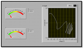
For the manual test, the graph become as exactly but when try it with the LabVIEW, there are some problems when the graph doesn't come out as the actual. The graph become opposite of the actual graph. The input from PV is separate into two that is current and voltage but the graph of both is combine (IV curve) to see the performance. But the LabVIEW only can accept 10v for voltage and 58mA for current. Since the output from PV is 21v for voltage and 0.4mA for current, it is a little high for LabVIEW to accept. So, the voltage divider and current divider being use to control the output from PV to become small enough for LabVIEW to accept. The voltage divider will divide the output from PV into 2, so the input into LabVIEW will become 10v and it exactly the amount that LabVIEW can accept. For that, 1kΩ is used. The current is used 6 resistor of 82Ω that connected in parallel to make sure the input is 50mA since the maximum current is 58mA. When test the circuit with LabVIEW, it worked but the graph is still not the actual graph.
- To improve the IV curve characteristic
- To testing the circuit and get the output produce from PV module
METHOD
- Firstly, test the circuit if it can produce the amount that I want
- Then, connect the circuit to the LabVIEW and observe the graph
Figure 1: Voltage Divider and Current Divider
Figure 2: LabVIEW
Figure 3: Graph IV Curve
RESULT
For the manual test, the graph become as exactly but when try it with the LabVIEW, there are some problems when the graph doesn't come out as the actual. The graph become opposite of the actual graph. The input from PV is separate into two that is current and voltage but the graph of both is combine (IV curve) to see the performance. But the LabVIEW only can accept 10v for voltage and 58mA for current. Since the output from PV is 21v for voltage and 0.4mA for current, it is a little high for LabVIEW to accept. So, the voltage divider and current divider being use to control the output from PV to become small enough for LabVIEW to accept. The voltage divider will divide the output from PV into 2, so the input into LabVIEW will become 10v and it exactly the amount that LabVIEW can accept. For that, 1kΩ is used. The current is used 6 resistor of 82Ω that connected in parallel to make sure the input is 50mA since the maximum current is 58mA. When test the circuit with LabVIEW, it worked but the graph is still not the actual graph.
Saturday, 6 April 2013
aChIng
OBJECTIVE
RESULT
- To expose student about aching
- To give understand more about project
METHOD
- Draw the circuit
- Apply the circuit in PCB layout
- Draw the PCB layout using PCB pen
- Put the circuit into the acid aching until only circuit drawing that left
- Remove the PCB pen using toner until the cooper that left and DONE
RESULT
CONCLUSION
This step is the simple way to do the aching. There are also other way that have to use UV printed and then aching. This UV is little difficult since the connection is easy to cut when it small. This aching is easy and can just do it at room. After finish aching, I have to drill a hole for placing components at the circuit.
Subscribe to:
Comments (Atom)


